How I converted a “dead” Apple MacBook to a Mac Pro Ultra Mini

A Little Background: I was given a “dead” 13″ MacBook that had water poured on it. After taking it apart and testing I found that the motherboard was still good but everything else was dead. The screen, dvd drive, battery, hard drive, ram, left speaker, CPU fan, top case / keyboard all were fried. Water seems to be a very good tool in making an $1,100 paper weight.A few hours of solder / hot-gluing I got it up and running with new ram and a new hard drive. I re-soldered the cooling fan and the right speaker to get them working. The left speaker connection was dead on the motherboard. The airport card “sees” wireless networks but fails when trying to connect, but the Ethernet port worked. I ran the unit for a few weeks with an external monitor with no problems. It works great as a multi-media machine for my LCD TV.Browsing the web I found a Mac Mini Mod to make it look like a Mac Pro. I started thinking it might be fun to make 20% of a MacBook look like Mac Pro Ultra Mini. Looking at the motherboard I found it was slightly larger than a full sized hard drive. Next I found a few external hard drive cases that looked like a Mac Pro. The first one I found was the iomega UltraMax Pro 33744 Hard Drive. I couldn’t find a retail site that sold just the case and at almost $450 was not an option. Then I found the Macally G-S350SUA Aluminum External Enclosure for only $40.It looked like a Mac Pro, front mounted power button, & all aluminum case.

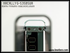
The PDF manual and all the specs I could find listed did not specify the overall case size. I enlarged the PDF to the actual size scale using the FireWire port to judge scale. The MacBook’s motherboard is 4.83″ x 7″ inches and doing an estimation I found that the board just might fit in the case. I also found a Flickr set that had these images. Looking at the construction I figured I could mod the case to support the motherboard and still have it open up if needed for service.

Once the case arrived (UPS lost it for a week) I set to work taking it all apart and seeing what I had to work with. Click on the images for a larger view
 |  |
 |  |
 |  |
I quickly saw the motherboard wasn’t going to fit without cutting off the bottom of the HD case. I did see that the case would be tall enough with the legs to house the motherboard. I also measured for thickness to see if the notebook hard drive would fit once the motherboard was mounted. Next I cut parts off of the inner hard drive mount so that all ports would be accessible from behind. After a few extra cuts and grindings I was ready to attach the motherboard.
Looking at the old Macbook case all the motherboard support mounts were molded into the plastic case. I decided to reuse some of the plastic, removed all of the metal frame, and cut it down to size. Next I placed small holes in the plastic near the hard drive mount holes on the external hard drive mount frame. I then zip-tied the old case to the frame. I was going glue or screw it in place but this gave me some adjustment room if needed. You can see the cut case and frame below.
 |  |
 |  |
You can see the first dry fit below

Next came cooling. I placed 3 1/2″ holes on the top for the cooling fan. I placed the metal on a wood box to support it while drilling with the drill press.
 |  |
 |
 |  |
 |
Carefully removing the ribbon connection under the track pad and then removing the extra pins, I soldered the red lead to the 4th pin. I then scraped off some of the protection coating and soldered the black wire to the ribbon’s ground wire. I did not connect the green wire which powers the blue LED built into the power button. The LED is much too bright when the lights are out in my living room.

After covering the connections with a hot glue gun I did several tests insuring a good connection and that no short-circuits were occurring on the other pins. Side note: I solder about as well as I weld, both are not pretty but they hold 
Next step was to mount the hard Drive. The original configuration used a long cable for the SATA connection so I had some options. My first thought was about heat so I did not want to mount it above the cooling fan. Looking at the old case the hard drive is stored inside a metal frame. Removing just the “cage” I made a few holes in it. I used longer screws in one of the CPU heat-sink and the wifi card. I added some hot glue to the bottom where any contact might be made to prevent shorting. This still allowed the unit to slide into its housing while providing a strong mounting spot. I ran before and after temperature tests using Hardware Montior and found the new configuration runs just a few degrees hotter.
 |  |

You can also see I mounted the magnetic power connection on top of the Ethernet port. I also temporarily added electrical tape to the top of the ram and board to keep down the chance of electrostatic sparking from the desk. The working right speaker & “sub woofer” are also mounted up front. The IR and white LED where damaged by the water.
Last I slid it back into the outer case and put a small bar with a screen on it in the center of the back of the case to keep the outer and inner case parts from moving. That was it! I now have a Ultra Mini Mac Pro. I’ve watched a few HD Movies and did some stress test to make sure it would not over heat and all is well. After a week or so I’m going to take the out case down to the local high school and use the laser etcher to place an Apple logo on the side. I will post the finished photos here along with more shots of the finished case.


Purchasing a new television involves numerous decisions. There are a number of viable options for the placement of a plasma or LCD television. These space saving flat screens can be mounted on the ceiling, on the wall, or placed on a stand so the LCD TV brackets are the great choice for mounting the TV sets.
ReplyDelete